

Instead of guessing speeds, we find the exact volumetric limit of your filament and build a reliable print speed profile on real data.
Most speed profiles are based on trial and error. This one is built on your filament’s actual flow limit in your conditions.
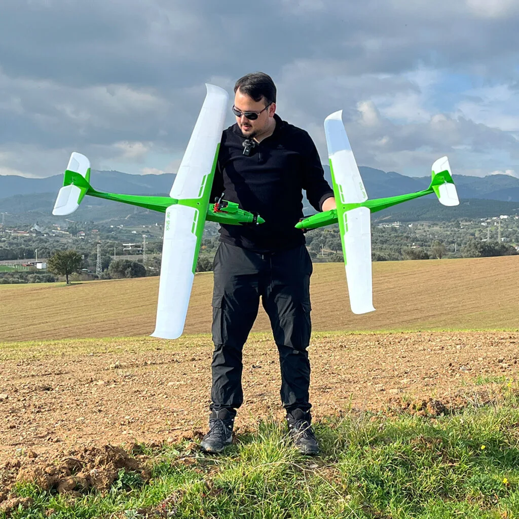
We are obsessed with that since our models are built around single-wall structures, controlled wall thickness, and predictable part weight. Because of that, this procedure focuses on two critical goals: strong layer adhesion and accurate printed weight.
This is one of the most important steps for getting stronger, more reliable Craycle planes, even with Regular PLA.
For PLA, strength differences caused by print speed may not always be noticeable, especially if your printer and filament are in good condition and your environment is stable, like during warmer seasons. However, with engineering filaments such as ABS and ASA, knowing the correct speed and temperature becomes critical. These materials are highly sensitive to print parameters, and layer adhesion is directly affected by them. In fact, ABS or ASA printed at incorrect settings can end up weaker than PLA.
This procedure is designed to help you build a repeatable filament profile for your conditions and your filament type.

⚠️ Important Notice!
Make sure your Printer, Filament, and Process Profile are selected as the default, standard and clear profiles for your printer brand before starting. Previous changes can affect these calibration tests in unexpected ways, so it is best to build the profile again from a clean starting point.
We are also recommending making the flow rate 1.0, layer height 0.18 mm and line width 0.40 mm everywhere before starting to test.
We use a 5-step workflow:
- Temperature calibration
- Maximum volumetric speed calibration
- Speed profile generation
- Pressure Advance calibration
- Reference wing test print and weight verification
1. Temperature calibration
The first step is to find the highest temperature that still gives clean print quality.
This is important because the next steps will push the filament toward its real performance limit. If the temperature is too low, layer bonding will suffer. If it is too high, stringing, soft edges, and unstable overhangs will appear.
Use a standard temperature tower. Start slightly above the manufacturer’s suggested range, then step down in regular intervals. For PLA, a tower from 240°C down to 210°C is usually a good starting point.
When you inspect the result, do not just look for the cleanest surface. Look for the highest temperature that still gives:
- Low stringing
- Clean overhangs
- Clean bridges
- Stable surfaces
- Good layer integrity
That temperature will be your working nozzle temperature.
Important: this test only makes sense with a dry filament and a healthy printer. Wet filament can create foaming, excess stringing, and false surface defects, which can push you toward the wrong temperature. A bad printer can cause stringing and surface issues as well.
Click for OrcaSlicer’s official Temp Calibration Article
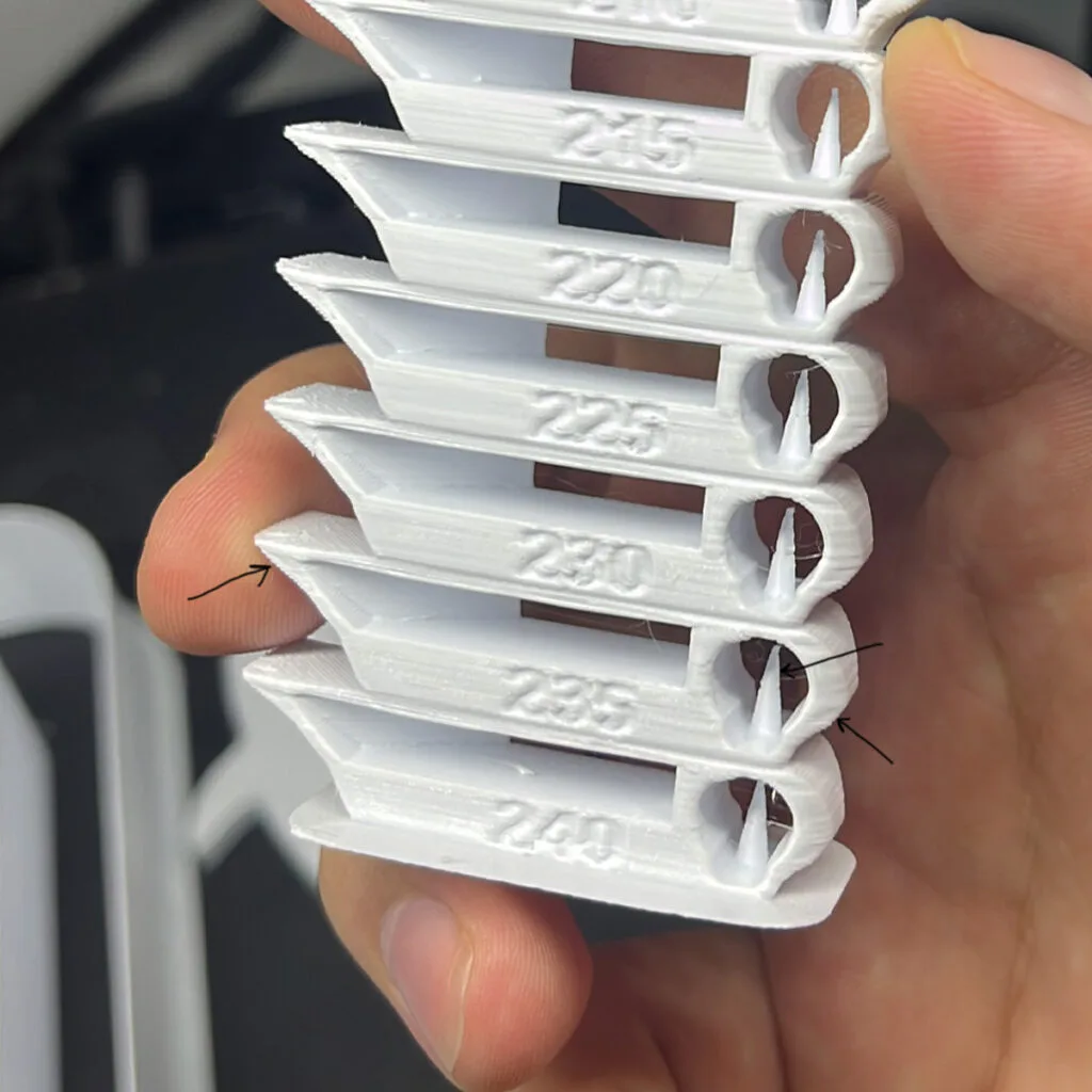
2. Maximum volumetric speed calibration
Once the temperature is fixed, the next step is to find the maximum safe volumetric speed for your filament, printer, and print conditions.

This test starts at a low flow rate and gradually increases it. As the print speed rises, the filament eventually begins to print too cold for proper bonding. At that point, layer adhesion drops, the surface usually changes, and the part starts losing strength. But it doesn’t mean that the slowest print is the strongest layer adhesion! You have to find the optimal flow speed by doing a strength test.
For RC aircraft parts, visual quality alone is not enough. The real goal is to find the highest flow rate that still gives strong and reliable layer bonding.
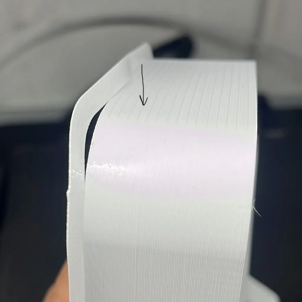
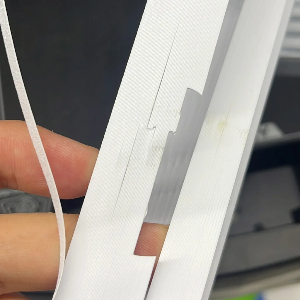
Surface appearance can help, but it should never be the only decision point. In PLA, the glossy sections often show the best bonding. In PETG, we observed the opposite in some cases, where the matte transition zone was actually much stronger than the glossy one. Different filaments can respond in very different ways, so the most reliable method is to physically test the printed model. A simple and practical approach is to apply force with pliers and progressively break the test part from the top down to identify where bonding starts to weaken.
That transition is the point you are looking for.
If you want a more reliable result for engineering materials, do not test only at one temperature. After completing the first temperature calibration, print the volumetric speed model again at the selected temperature, then slightly above and slightly below it (+-5 or +-10 degrees). This makes it easier to see which temperature gives the widest strong bonding range across the model.
In many cases, the best working point is not the single strongest spot, but the middle of the broadest stable range. This is especially important for PETG, ABS, ASA, and other engineering materials, which can react more sensitively to temperature changes. For PLA, this extra step is often less critical, but for more demanding materials it can make the final speed profile much more accurate.
OrcaSlicer’s calibration guide also includes a dedicated maximum volumetric speed test and shows how to read the final value in Preview.
Click for OrcaSlicer’s official Volumetric Speed Article
3. Speed profile generation
(This step is going to be a little complicated, but we have developed a great tool (Speed Profile Generator) below for you.)
Once you know the safe volumetric speed, you can convert it into a real print speed. This speed is the maximum printing speed that gives you the best layer adhesion at your calibrated temperature.
This is the key formula:
Volumetric speed = line width × layer height × print speed
So the real print speed is:
Print speed = volumetric speed / (line width × layer height)
Example Calculation
Let’s use this reference setup:
Volumetric speed: 8 mm³/s
Line width: 0.40 mm
Layer height: 0.18 mm
First, calculate the extrusion cross-section: 0.40 × 0.18 = 0.072 mm²
Then divide volumetric speed by that area: 8 / 0.072 = 111.1 mm/s
So in this example, the correct print speed is: 110 mm/s (Rounded)
Print speed will be applied to the Outer Wall Speed and this is the reference speed for the rest of the profile.
Speed multipliers
Since you have the most important value, the outer wall speed, you do not need to calculate the entire profile from scratch every time. You can use a simple set of multipliers.
Outer wall: X (This is the reference Print Speed)
Inner wall: 1.25x
Small perimeters: 0.65×
Sparse infill: 1.50×
Internal solid infill: 1.25×
Top surface: 1.00×
Gap infill: 1.25×
First layer: 0.33×
First layer infill: 0.50×
Initial layer travel speed: 60%
Overhang/Bridge speeds, keep these as percentages
These values are already normalized, so you can keep them as percentages and apply them directly to your outer wall speed:
10% to 25% overhang: 50%
25% to 50% overhang: 40%
50% to 75% overhang: 30%
75% to 100% overhang: 20%
External bridge: 45 mm/s
Internal bridge: 135%
This approach keeps the profile easy to scale. Once you find the correct Print Speed (outer wall speed) for your filament, the rest of the profile follows naturally.
If this step feels a bit complicated, that’s completely normal. The tool below can help simplify the process.
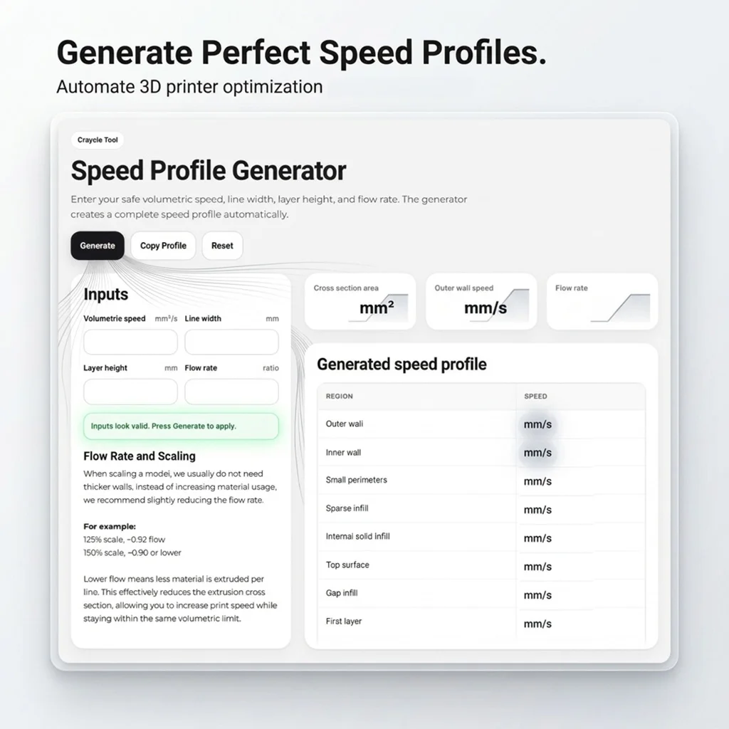
⚡ Speed Profile Generator
If you prefer a simpler approach, you can use this tool to handle these calculations for you. Just enter your basic values, and the full profile will be created automatically.
This tool can save time and help you avoid small calculation mistakes, especially when working with different filaments or projects.
The Generator also includes the flow rate adjustment for the scale models in calculations.
Key Advantage is Scalability!
By adjusting the line width based on the scale ratio and choosing a suitable layer height, you can preserve consistent extrusion conditions.
For example, at 125%:
Line width: 0,50mm
Layer Height: 0,22mm
This makes it possible to maintain similar layer adhesion across different model sizes, nozzle diameters, and layer height preferences.
4. Pressure Advance calibration
After temperature, volumetric speed, and your final speed profile are locked in, you can calibrate Pressure Advance.
This order matters. Pressure Advance depends on how quickly pressure builds and relaxes inside the nozzle, so it should be calibrated after the real speed profile is established.
OrcaSlicer includes dedicated Pressure Advance calibration tools and officially supports multiple methods, including Tower (Recommended) and Line methods, with separate variants for Direct Drive and Bowden extruders. Orca’s own calibration guide also shows the simple tower logic: choose the best height, then calculate the PA value from that height and the configured PA step.
Simple PA Tower calculation
Use this formula:
K = Start PA + (Selected height in mm × PA step)
Example Calculation
Start PA: 0
End PA: 1
PA step: 0.002
K = 0 + (16 × 0.002) = 0.032
So the final K value is: 0.032
Click for OrcaSlicer’s official Pressure Advance Article
5. Reference Test Print and Weight Check
Once your profile is ready, the final step is not another visual test.
This is a reference-based weight calibration, which is critical for RC aircraft printing.
🔽Download the Filament Calibration Files
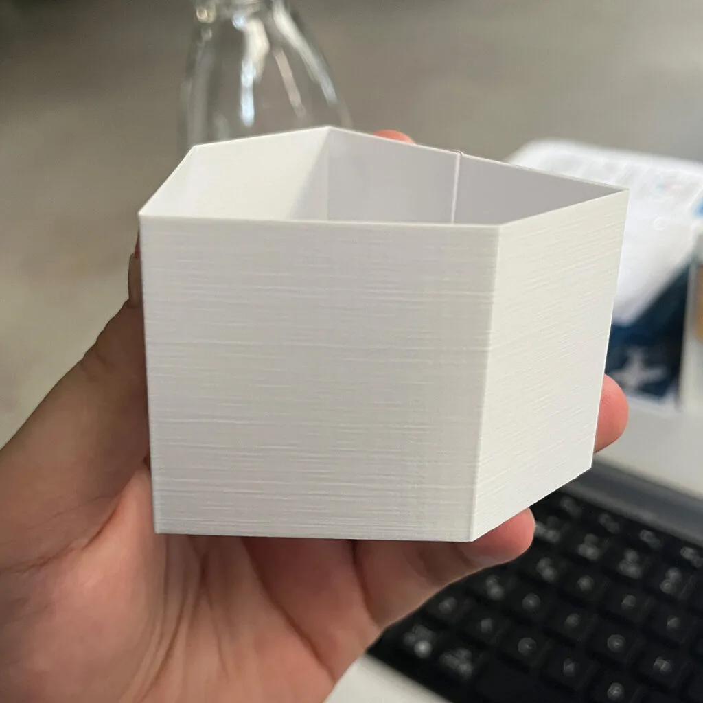
At this stage, you will print a dedicated Craycle Test Part using the exact settings defined in the provided project file. This geometry reflects typical Craycle structures, so the result is directly transferable to real builds.
We made the test part from a wing part that contains almost all the techniques we invented for the Craycle Planes so far. Therefore, you don’t test only the weight; you also test the various geometries we use in our models.
Files included:
STL file of the Test File
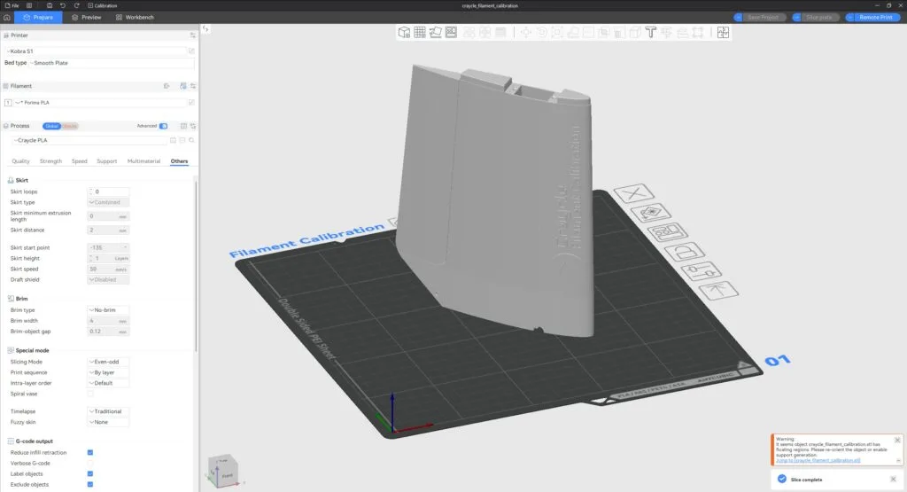
3MF project file with all settings pre-configured (Double check the settings below)
You can use the project file directly, or apply the same settings manually.
⚠️ Make sure your print uses these exact settings:
- Line width: 0.40 mm
- Layer height: 0.18 mm
- Single wall only
- No top layers
- No bottom layers
- No infill
- Flow: 1.00 (in slicer)
- Wall generator: Classic
- Slice gap closing: 0
- Slicing Mode: Even-odd
Target weight and flow calibration
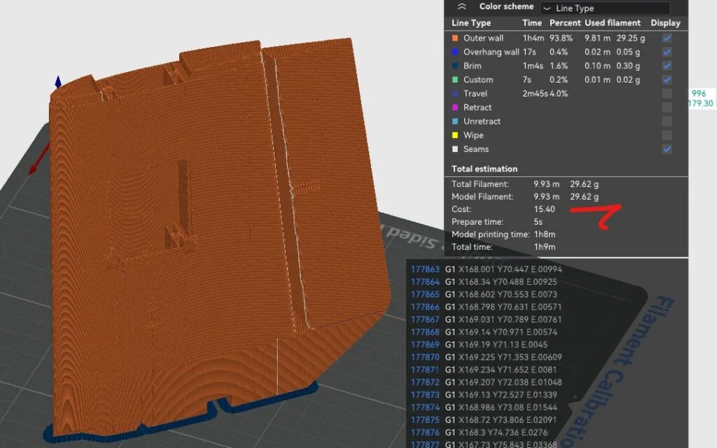
This test part is designed around a fixed reference weight of 29.6 g, and this value is the foundation of the entire calibration process. First, slice the model and check the estimated weight. It should be close to 29.6 g. If it is not, do not adjust the flow yet; this usually means something is off in your slicing setup, such as line width, gap fill, or extra walls.
Once the slicer value looks correct, print the part and measure its real weight. If the printed result is also close to 29.6 g, your extrusion is already well calibrated. If it is heavier or lighter, you need to correct the flow.
For this method, we recommend keeping the slicer flow at 1.00 and applying the correction directly on the printer side, for example, using a Start G-code command like M221 S95. We have tested this approach on the Creality K1 and confirmed that it works reliably. The reason behind this is simple: the slicer keeps its reference weight stable while the printer applies the real correction during printing.
However, some printers may ignore commands like M221. If that happens, you can calculate the correct flow using this formula: 29.6 divided by the printed weight. Then apply this value using the method your printer supports. If this changes the slicer’s estimated weight, you can adjust the filament density to bring the slicer value back to 29.6 g.
🎯 The goal is simple: your slicer should stay close to 29.6 g, and your real printed part should match it.
Better if you can also measure the wall thickness by breaking the test part somewhere in the middle and measuring the cleanest single wall area with a caliper (Wall thickness should be 0.40 – 0.42 mm).

Final result ✅
When this procedure is done correctly, you end up with the best slicer setup in your conditions!
This procedure is not only useful for Craycle models or RC planes. It can help you get stronger prints, better layer adhesion, and fewer printing problems in many other models and materials as well. It’s also very important for your printer to have correct temperature and speed settings to keep the extruder working under better conditions. This will affect the lifetime of the printer for sure!
Please let us know if anything feels missing or unclear. And please share your test results with us. We would love to see what you print and how much gain you got with this calibration.
If you are a content creator, I think this is worth a video. Once you complete this calibration, I believe you will agree with it.
Best Regards,
Cemal Ozcelik / Founder of Craycle
